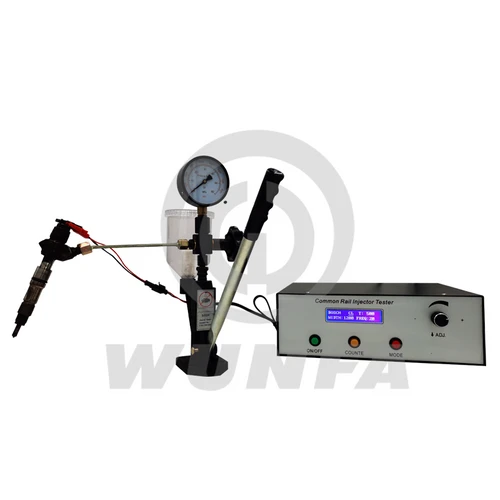
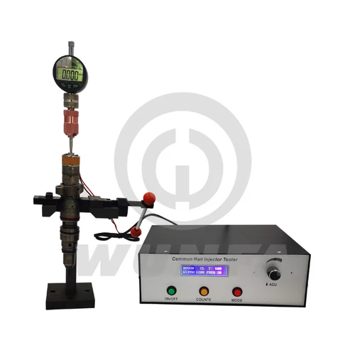
1. Accessories and Interface Description
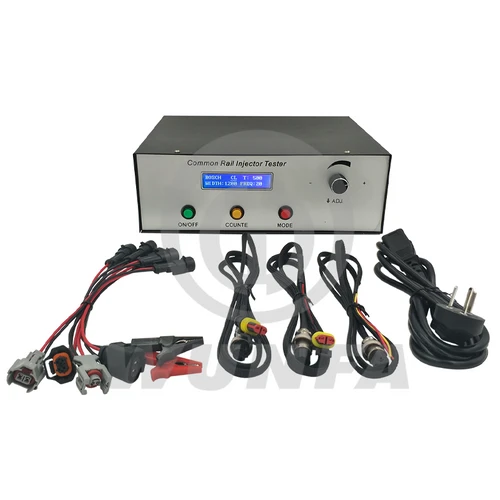
1.1 Check the Accessories
After receiving the goods, please open the box and check box items are consistent with the packing list. If any parts are missing, please contact the service personnel.
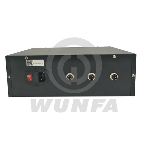
1.2 Chassis Interface
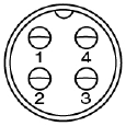
Electromagnetic injector end (2-pin)
| Description | Air outlet side |
|
| Injector drive | pin1 | |
| Injector drive | pin2 |

Piezo injector end (4-pin)
| Description | Air outlet side |
|
| Injector drive | pin1 – | |
| Injector drive | pin2 + | |
| Empty | pin3 | |
| Empty | pin4 |
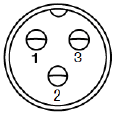
Count switch terminal (3-pin)
| Description | Air outlet side |
|
| Count Normally open | pin1 | |
| Counting common | pin2 | |
| Counting Normally closed | pin3 |
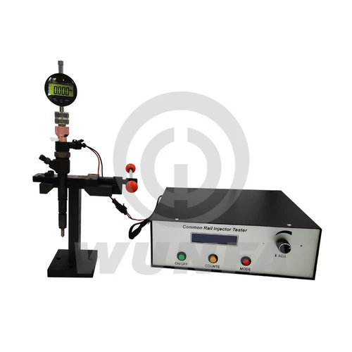
2 Operating Instruction
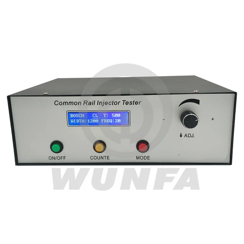
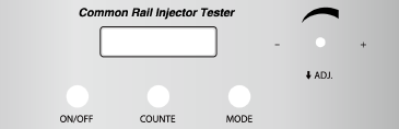
2.1 Chassis Pan
2.2 Basic Operation
2.2.1 Display interface
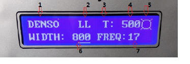
1. Select the type of injector: BOSCH、DENSO、DELPHI、CAT-L、CAT-H、PIZEO
2. Current Injector conditions: VL、VE、LL、TL
3. the injector count method: T: according to the number of counts;
4. injector counting time: T :0-2000 times
5. Injection signs: icon display indicates the beginning of the injector fuel injection;
6. pulse width: 100 ~ 3000uS;
7. injection frequency: 1 ~ 30Hz
8. The count flag: The icon display indicates that the injector starts counting.
2.2.2. Key Features
2.2.2.1 ON/OFF button On/Off Injector;
2.2.2.2 COUNTE button Start/stop counting.
When the number is 0, the injector has been working; do not stop.
2.2.2.3 MODE button:
A, short press MODE button to switch to a different injector condition. (BOSCH, DENSO, DELPHI, CAT-L, CAT-H, PIZE)
B. long-press the MODE button to switch between test patterns and resistance injector test mode;(Valid only when the injection is stopped)
C. After entering the resistance test mode, connect the injector first, and press the ON/OFF button once. After 2 seconds, the resistance of the injector will be displayed on the screen. The unit is milliohm.
If it is found that the measured resistance deviates greatly from the actual resistance, it should be calibrated.
Calibration method: In the resistance measurement interface, short-circuit the two injector clips, then press and hold the “Count” key. A “#” symbol will appear at the upper right of the screen. After this symbol disappears, calibration is completed.
The screen listing shows 0 mohm.
2.2.2.4 ADJ knob: Consists of two parts, a function
A. Common parameter settings
The first step is to short-press down to select the setting of the project. There is a corresponding position cursor display, divided into: Injector brand choice/count value/width/frequency, cycle through the four setting items, the current cursor location for the selected projects; The second step, Rotate Left or Rotate Right, modifies the item’s current value.
3 About Maintenance Responsibility
1. Under normal use, due to product quality issues, free repair within one year.
2. Due to the non-standard use, causing damage to the product, the user bears the maintenance costs;
3. The product’s life-long maintenance, a year later, users bear the maintenance costs.


Reviews
There are no reviews yet.